Tact Switch Handwired Keyboard (Part 2)
Recap
This is a continuation of my attempt to build a hand-wired mini keyboard. I discussed the main inspiration, design and the plan of action in the first post I made on the topic. Let me do a quick recap.
What is it:
- A small keyboard that can be held like a controller, and typed with thumbs
- For use as a media center remote: wireless (Bluetooth), and has buttons on the side (to be used as a remote)
How to make it:
- Use a handy cardboard box as the housing (17.5mm x 9.2mm x 3.2mm)
- Use 12x12mm tact switches with caps
- Hand-wire the switches to a nice!nano microcontroller
Finding a switch plate
Having found my cardboard box, I ran into another problem. The switch with the cap attached is too high, so if I attached the pins to the outside of the box, the switches would bed raised more than a centimeter from the box’s surface. That means I need to attach the switches to another surface which is recessed into the actual box. In other words, I needed, what’s called in the biz, a switch plate.
I found another random cardboard, took an Xacto knife to it to make holes for the pins on the switches. That seemed to work well enough, but with the switches as close to each other as possible, I feared that the cardboard might start to flex after a few days of usage. Looking around my room for an alternative, I found an empty box of chocolates. Bingo! I used the knife and a ruler, and made some markings:
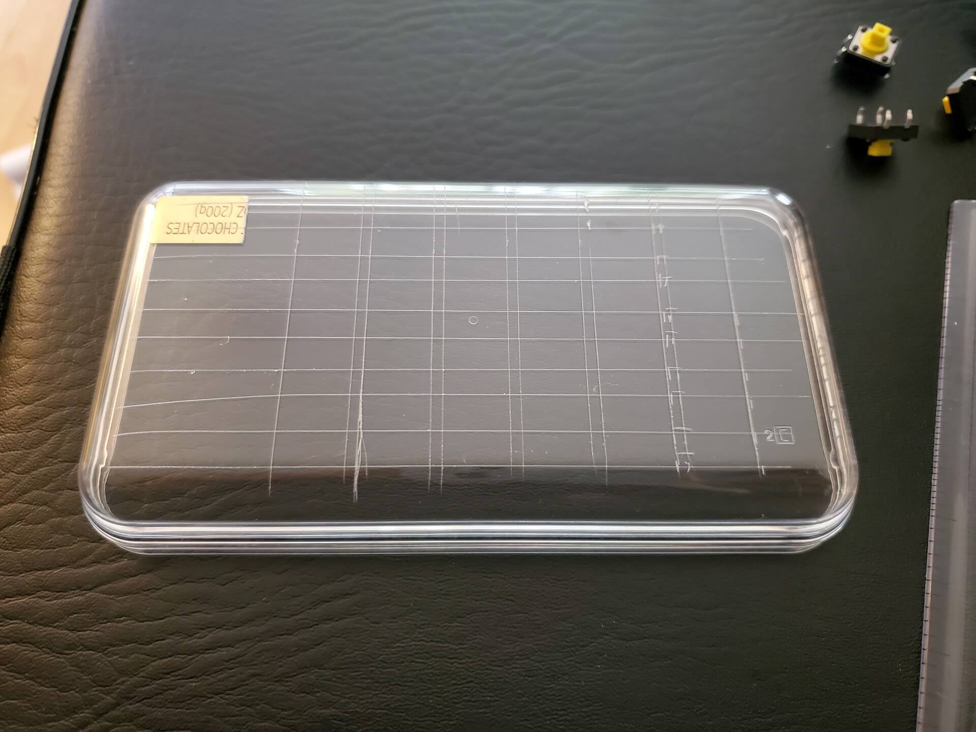
Then I heated up my soldering iron and poked holes in the right places. I had to open the windows and turn on the exhaust fan to get rid of the burned plastic smell. To be honest I’m not sure if it’s toxic to any degree, I should’ve wore a mask as well. Something I will look into for sure, but it’s not often I burn plastic, so I suppose this one time is OK.
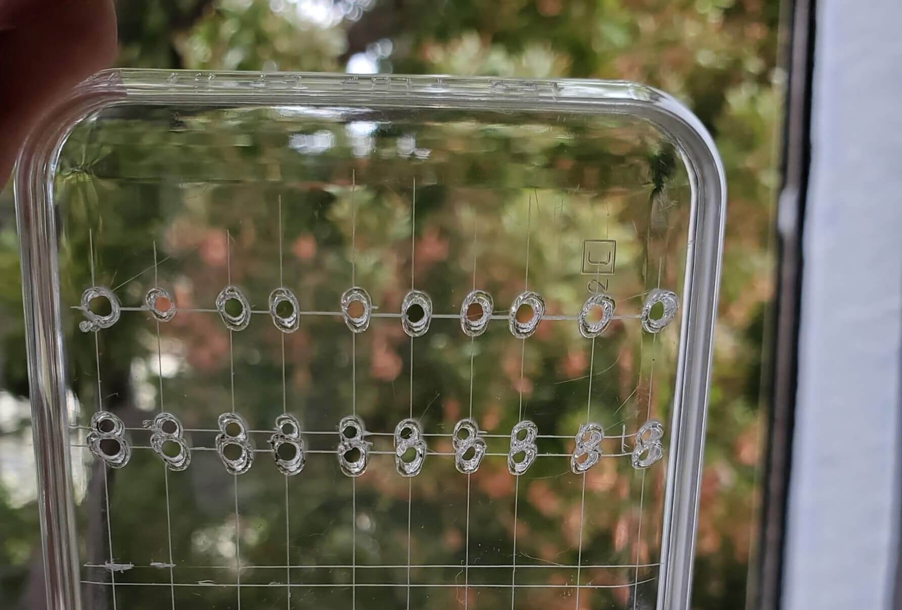
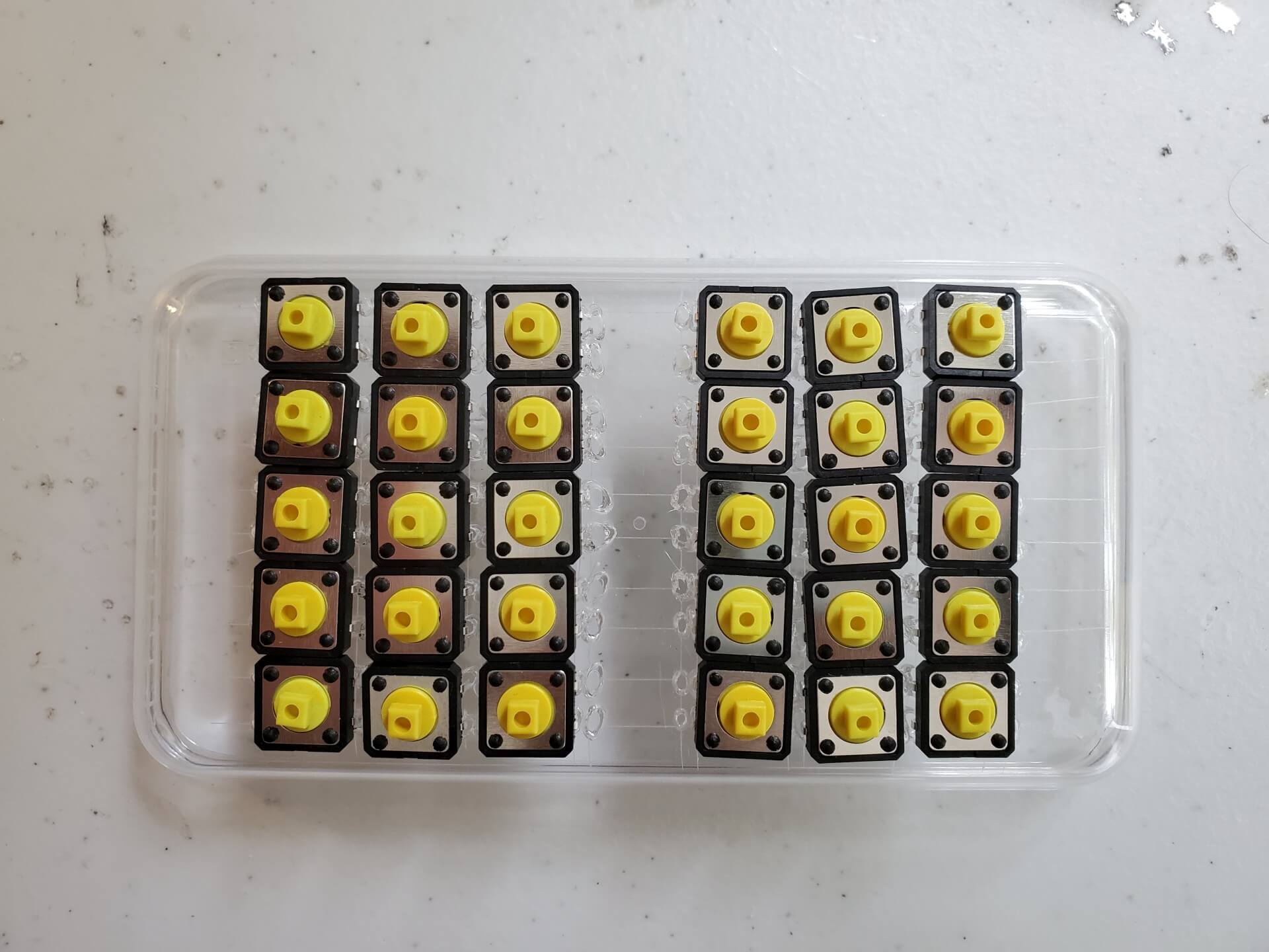
Then come the switches. My measurements seemed to be reasonable, but the burning is not accurate, so the switches are not that well-aligned, but good enough. I also found that after pushing each switch into position, I couldn’t bend the pins all the way to secure the switch. While most switches wouldn’t fall off, some of them did, and some that stayed in place were wobbly. This is not ideal by any means, but I needed a first draft to improve upon, so I was OK with it. Here’s a picture of all the switches attached:
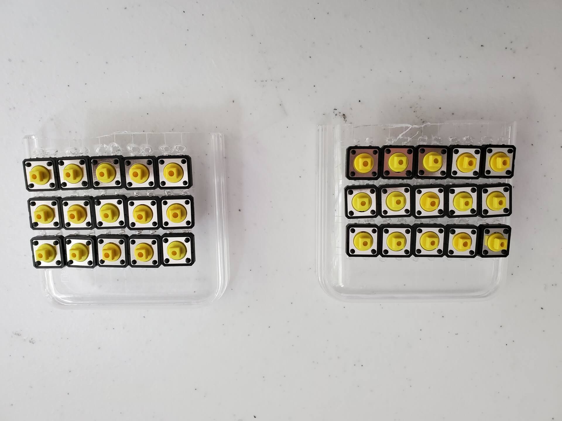
Next up, break the plate into two halves so that they can be separated to whatever distance or angle I like:
I then cut up holes in the box, fixed the switches from the inside, and started attaching the caps:
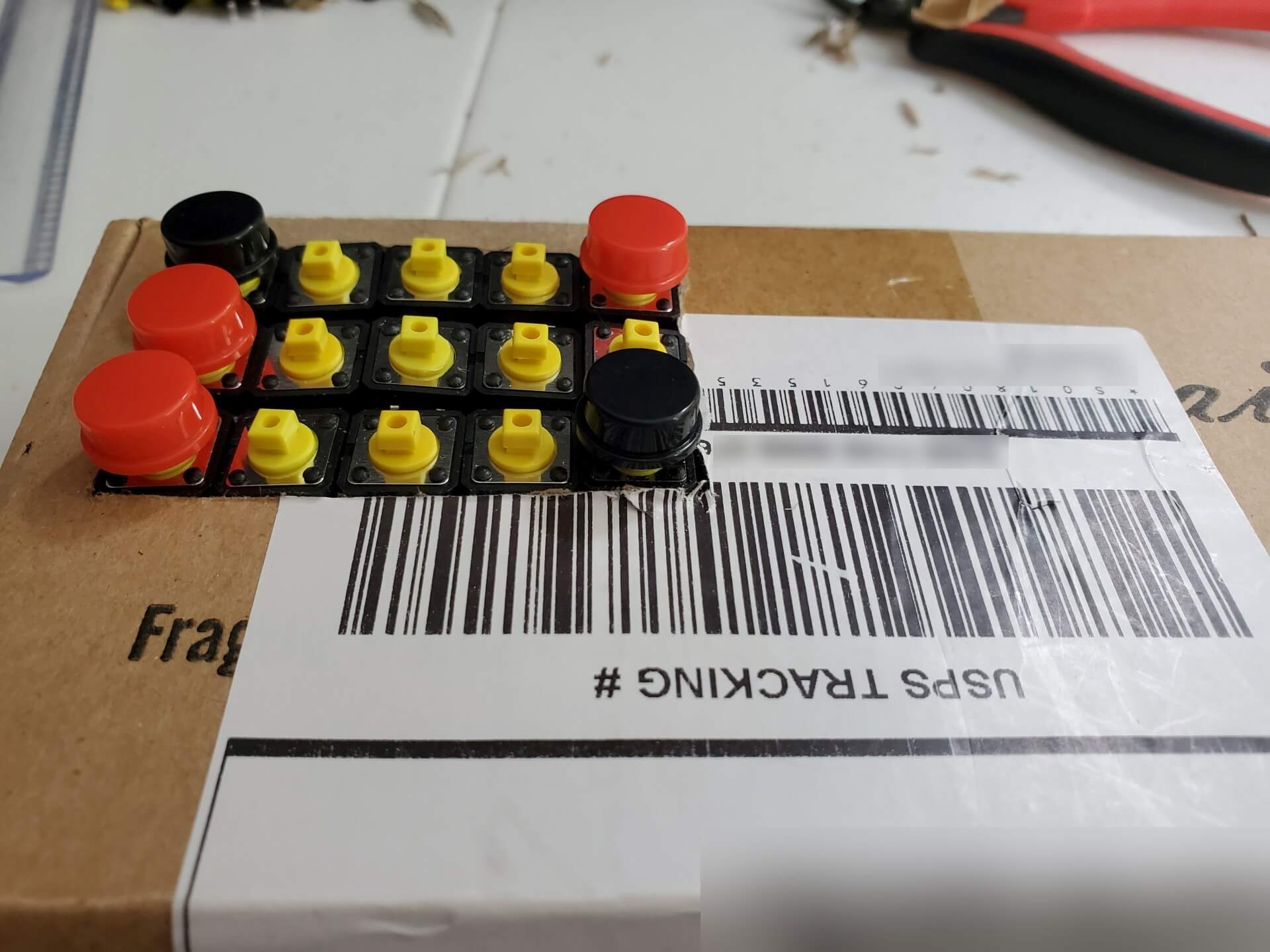
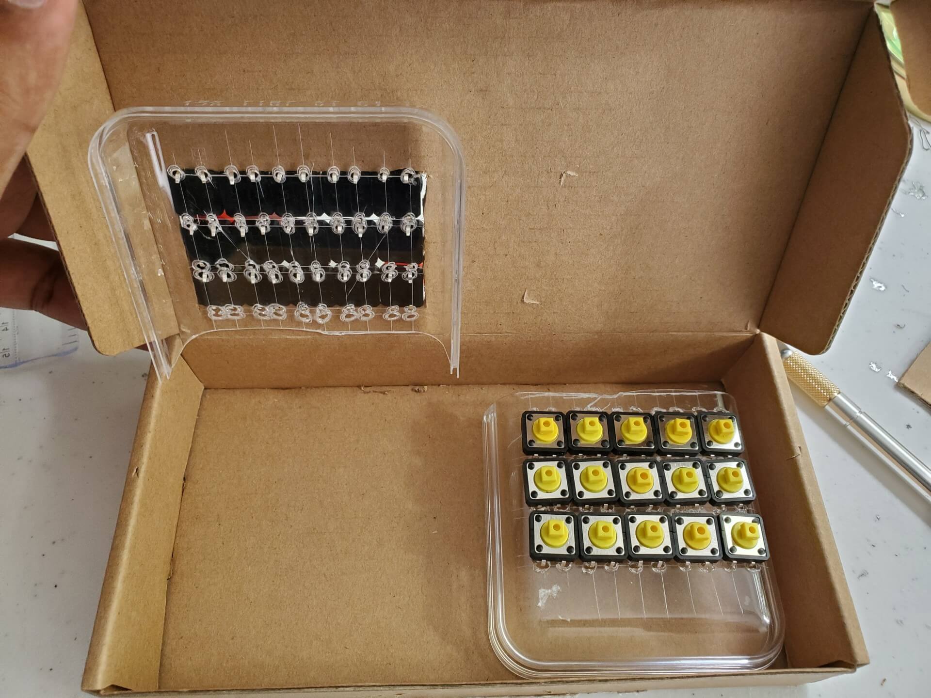
When I started putting more caps in though, I realized that the caps have a larger footprint than the switches, and that the switches are too close to each other:
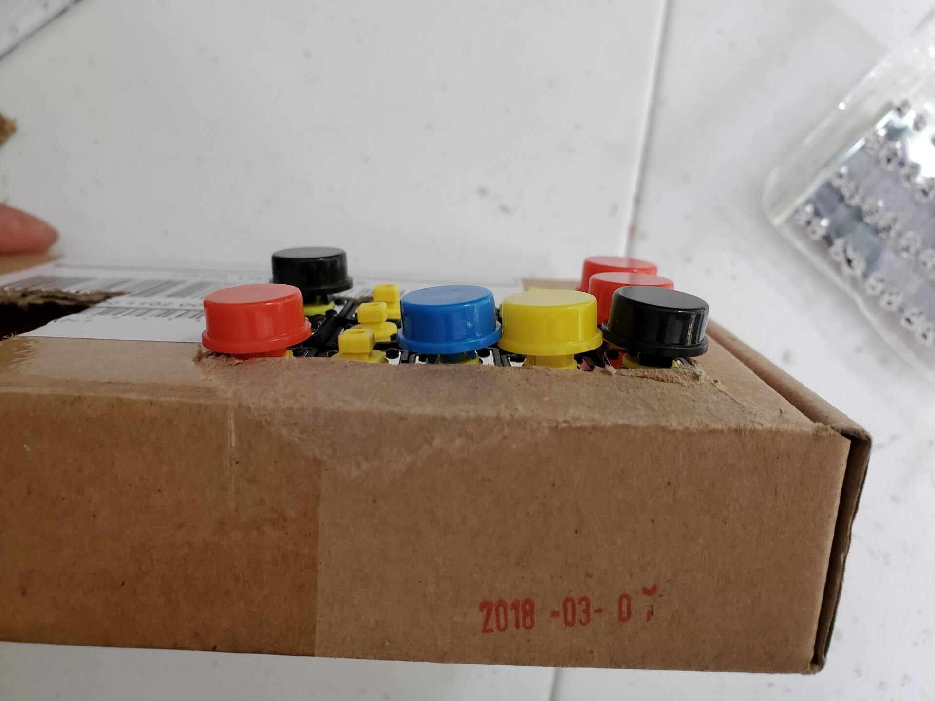
Oops. I didn’t see that coming. I should have measured the caps before I started. At this point, I could have started over with another plate (I eat a lot of those chocolates), but the manual approach turned out to be too finicky anyway. So I decided to go another route and ordered a set of 5x7cm solderable breadboards to serve as the switch plates for $6.
If I was so inclined, I could have started looking into designing custom PCBs and getting them fabricated, like so many in r/mechanicalkeyboards seem to be doing for cheap, but that’s a rabbit hole I’ll dive into later (too much cognitive load in my life right now as it is).
That’s all folks, thanks for reading!